
What is a Subsystem?
Pull the back off any complex machine and you find the same thing: it is not one system, it is a stack of smaller ones, each doing a job. To the engineer who builds it, a car is not “a car” — it is a propulsion subsystem, a braking subsystem, a steering subsystem, and an electrical subsystem, all wired together and handing work to each other. That is what a subsystem is: a self-contained part of a larger system that performs a specific function and interacts with the other parts to make the whole thing work.
Why split a system up at all? Because complexity does not scale. One engineer can reason about a braking subsystem — its inputs, its outputs, the ways it can fail — in a way nobody can reason about an entire vehicle at once. Break the big problem into subsystems and each becomes small enough to design, test, and verify on its own before you bolt them together. Get the split wrong, though, and the seams between subsystems become exactly where the system fails. This guide covers how subsystems are defined, built, verified, and integrated — and where the traps hide.
Examples of Subsystems in Real Systems
The fastest way to see what a subsystem is, is to look at a few real systems and the parts they break into:
| System | Its subsystems | What each one owns |
|---|---|---|
| Car | Propulsion, braking, steering, electrical, climate | Go, stop, aim, power, keep occupants comfortable |
| Airliner | Avionics, propulsion, hydraulics, landing gear, environmental control | Navigate & control, make thrust, move surfaces, take off/land, keep the cabin liveable |
| Laptop | Processor, memory, storage, display, power, cooling | Compute, hold working data, store files, show output, supply power, stop it overheating |
| Smartphone | Processor (SoC), battery, radio/antenna, camera, display | Run everything, power it, connect it, capture images, present the interface |
The Subsystem Decomposition Template
Knowing what a subsystem is matters far less than being able to draw the line in the right place on your own system. This is the template we use to do it. Copy the table, put your system in the title, and fill one row per candidate subsystem. If you cannot complete a row, you have not found a subsystem — you have found a component, an organisation chart, or a wish.
| Column | What goes in it | The test the entry has to pass |
|---|---|---|
| Subsystem | A noun naming the thing, not the team that builds it | Rename the department tomorrow and this entry does not change |
| Function it owns | One sentence, one verb, no “and” | If you need “and”, you have two subsystems |
| Inputs | What must cross the boundary inwards for it to work | Each input is produced by something else on this list |
| Outputs | What it hands to the rest of the system | Each output is consumed by something else on this list |
| Interfaces to | The other subsystems it touches, by name | Fewer than four is usually right; more means the split is wrong |
| Allocated requirements | The parent requirements this subsystem is now on the hook for | Every system-level requirement lands on exactly one owner |
| Verified by | How you will prove it meets them, on its own | Test, analysis, inspection or demonstration — named now, not later |
The template, filled in: a battery electric vehicle
An empty template teaches nothing, so here is the same table completed for a battery electric vehicle — a system most people can picture, with genuinely hard boundaries. Note how every output in one row appears as an input in another: that closure is the check that the decomposition is complete.
| Subsystem | Function it owns | Inputs | Outputs | Interfaces to | Allocated requirement (example) | Verified by |
|---|---|---|---|---|---|---|
| Battery | Stores and releases electrical energy | Charge current, contactor commands, coolant | DC power, state of charge, power limits, heat | Propulsion, Thermal, Vehicle Control, Charging | Deliver 150 kW continuous for 30 s at 20 % state of charge | Test (dynamometer discharge profile) |
| Propulsion | Converts electrical energy into tractive torque | DC power, torque request, coolant | Wheel torque, regenerative current, heat, actual torque | Battery, Thermal, Vehicle Control | Deliver requested torque within ±5 % in under 100 ms | Test (step-response on rig) |
| Thermal | Holds every component inside its temperature band | Component temperatures, cooling mode command | Coolant flow and temperature, thermal fault status | Battery, Propulsion, Vehicle Control, Charging | Keep cell temperature below 45 °C during a 150 kW DC charge at 40 °C ambient | Analysis, then test (climatic chamber) |
| Vehicle Control | Decides what the vehicle should do and commands it | Driver inputs, status from every subsystem | Torque request, contactor commands, cooling mode, charge enable | All | Open contactors within 50 ms of a battery isolation fault | Test (fault injection) |
| Charging | Moves energy from an external supply into the battery | Plug state, supply limits, charge enable, coolant | DC charge current, plug state, heat | Battery, Thermal, Vehicle Control | Negotiate and hold supply current within the limit the charger advertises | Test (conformance against the charging standard) |
The interface matrix that goes with it
The decomposition table tells you what each subsystem owns. It does not tell you what has to be agreed between two teams before either can build anything — and that is where projects actually fail. An N² matrix does. Read it as: the row hands the cell contents to the column. Every non-empty cell is an interface that needs a specification, an owner, and a test.
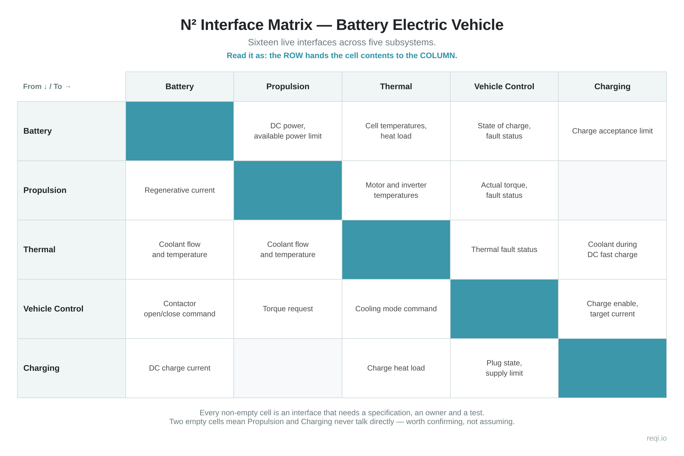
| From ↓ / To → | Battery | Propulsion | Thermal | Vehicle Control | Charging |
|---|---|---|---|---|---|
| Battery | — | DC power, available power limit | Cell temperatures, heat load | State of charge, fault status | Charge acceptance limit |
| Propulsion | Regenerative current | — | Motor and inverter temperatures | Actual torque, fault status | |
| Thermal | Coolant flow and temperature | Coolant flow and temperature | — | Thermal fault status | Coolant during DC fast charge |
| Vehicle Control | Contactor open/close command | Torque request | Cooling mode command | — | Charge enable, target current |
| Charging | DC charge current | Charge heat load | Plug state, supply limit | — |
Four traps this template catches
- The org chart in disguise. If your subsystems are named after the teams that build them, you have documented your company, not your system. The boundaries will move at the next reorganisation and every interface will move with them.
- The subsystem with no verification. A row whose “Verified by” column reads “integration test” is not a subsystem — it is a part. The whole point of the split is that each piece can be proven on its own before anything is bolted together. See verification and validation in systems engineering for what each method actually demands.
- The unallocated requirement. Every system-level requirement must land on exactly one subsystem. Land it on two and neither team will own it; land it on none and it will be discovered during acceptance. This is the discipline of requirement allocation, and a traceability matrix is how you prove it happened.
- The boundary drawn after the design. Decomposing a system you have already half-built produces subsystems that match the drawings rather than the functions. Draw the system boundary first, then the internal splits, then the design.
Subsystem Overview
Subsystems are crucial parts of larger, more complex systems. They exist as smaller entities within a broader context, each having its own unique role and function. This aids in breaking down a system’s complexity, making it easier to understand, develop, and manage.
Identification and Design of a Subsystem
The first step in any subsystem development process is identification. It entails breaking down the overall system into its component parts or subsystems. It takes into consideration the key functions, tasks, and processes of the primary system. The features and characteristics of a subsystem are designed during this stage. The design consists of several parts, such as subsystem configuration, operation protocols, and the definition of interfaces with other subsystems.
Subsystem Development and Modelling
Once a subsystem’s design is finalised, the development process begins. This involves the detailed engineering necessary to create the product or process based on the design parameters. Developers and engineers are responsible for translating the designed subsystem into a tangible, functioning entity.
Subsystem modelling is an essential aspect of the development phase. This process involves creating virtual models and simulations of the subsystem. It helps engineers to analyse design features, conduct tests, and pinpoint any potential issues before physical assembly and integration take place.
Subsystem Verification and Validation
Subsystem verification and validation is a critical part of the engineering process. Verification ensures that the subsystem is designed and built correctly, confirming that the subsystem meets the stated requirements of the design output. On the other hand, validation is the process of evaluating subsystem during or at the end of the development process to ensure that it fulfills the specified requirements for a particular use or application.
Subsystem Integration
Subsystem integration involves bringing together all the distinct subsystems into one unified system. This is a crucial stage in achieving a systematic interaction that ensures all subsystems work together harmoniously. Engineers need to carefully interconnect subsystems to prevent interferential or adverse operations, ensuring a smooth interplay of actions to achieve the primary system’s objectives. On a Vee diagram, this is the step from subsystem to system level on the right-hand arm, where each interface agreed during decomposition is finally proven.
Subsystem Analysis
Once a subsystem is in place and integrated, analysis is vital for troubleshooting, enhancement, and maintenance purposes. It examines reproducibility, reliability, and stress limit. This analysis identifies problems or inefficiencies within the subsystem, thus aiding engineers in making necessary changes to improve performance.
Subsystem Lifecycle Management
The subsystem lifecycle includes phases such as conceptualisation, development, utilisation, and retirement. Managing this lifecycle is crucial in systems engineering. With proper management, subsystems can be maintained efficiently, ensuring long-term system functionality.
Subsystem Requirements Engineering
Subsystem requirements are the detailed description of what a particular subsystem is supposed to do, outlining its restrictions and specific needs. Clear and accurate requirements help in designing, developing, and testing the subsystem, contributing towards a successful integration within the overall system.
A subsystem is a vital component in systems engineering, offering a route to address and manage the inherent complexity within most systems. Understanding these basics of subsystem handling provides a base on which effective systems professionals can design, develop, manage, and optimise complex systems. The destination of a successful career in systems engineering eagerly awaits those who navigate this journey with passion and determination.

From System to Component: A Worked Breakdown
The clearest way to understand subsystems is to take one apart. Start with a car — the system. Its job is “move people safely.” That splits into subsystems, each owning one part of the job: propulsion to go, braking to stop, steering to aim.
Now zoom into the braking subsystem. It is a complete system in its own right: a hydraulic part (master cylinder, lines, calipers), an electronic part (the ABS controller and wheel-speed sensors), and the mechanical pads and discs. Zoom into the ABS controller and you find circuit boards, firmware, connectors — components.
That is the whole idea: a subsystem is just a system viewed from one level up. Where you stop zooming and call something a “component” is a design choice — usually the point where it is bought or built as a single unit and not usefully broken down further.
Case Study: iPhone’s “Antennagate” Scenario
In 2010, Apple faced a significant challenge post-launch of its iPhone 4, stemming from an issue with one of its subsystems – the antenna. The new phone boasted a unique design wherein the antenna was integrated into the phone’s body. But, if users held the phone a certain way, it often led to a sharp drop in signal strength, a problem termed Antennagate. The performance of the antenna subsystem directly impacted the operation of the larger system, compromising the overall functionality and user experience of the iPhone.
Apple swiftly recognised the issue, addressing it in multiple ways. Firstly, they offered free cases that could solve the problem by insulating the part of the antenna that was causing signal degradation. Secondly, in their next edition, the iPhone 4S, they remodelled the antenna design based on their learnings, demonstrating adaptability and innovation.
The iPhone itself consists of an ecosystem of multiple subsystems aside from the antenna, such as the iOS operating system, the touchscreen interface, camera system, the chipsets, battery, and more. Each subsystem has its unique function but works seamlessly together to deliver the holistic iPhone experience users have come to value.
“Antennagate” underscores how critical each subsystem’s effective performance is for the whole to function efficiently. It demonstrates the challenges that can crop up from the smallest elements, stressing the importance of careful design, testing, and swift problem resolution in systems engineering. Thus, even the most experienced engineers and world-leading companies can encounter unexpected obstacles, reinforcing why systems engineering is vital in coordinating complex projects.
Related systems engineering guides
- What is the systems engineering V-model? — where subsystems sit in the lifecycle
- Systems vs subsystems: key differences — how the two relate
- What is systems architecture? — how the split into subsystems is decided
- What is systems integration? — putting the subsystems back together
- What is MBSE? — modelling subsystems and their interfaces
Frequently Asked Questions
What is a Subsystem?
A subsystem is a secondary or auxiliary system that functions within a larger, primary system. It performs specific tasks and operations that contribute to the overall functionality of the main system, enhancing its performance.
What is the role of subsystems in systems engineering?
In systems engineering, subsystems play crucial roles in breaking down the complexity of a larger system. Each addresses distinct functionalities, helping to develop, understand, and manage the main system more effectively.
What is the process of subsystem development?
The process of subsystem development includes stages of identification, design, modelling, verification and validation, integration, analysis, lifecycle management, and requirements engineering. These steps ensure that the subsystem can function as intended within the framework of the larger system.
What is subsystem integration?
Subsystem integration involves combining all the various subsystems into one coherent system. It ensures harmonious interaction of all subsystems, enhancing the performance and efficiency of the overall system.
Can subsystems operate independently?
Yes, subsystems can function independently. However, their performance and operations contribute to the broader system. While they can operate in isolation, effective subsystems are usually interconnected with other parts of the system to achieve a common goal.
What are some examples of subsystems?
Subsystems are found in various contexts. In a vehicle, the engine, transmission system, braking system, and steering system can all be considered subsystems as part of the larger vehicle system. In computers, the hardware, software, memory, and other functional units serve as subsystems.
How are subsystems in an iPhone integrated?
In an iPhone, subsystems like the operating system, central processing unit, camera, touchscreen control and display, audio system, antenna, memory system, and battery are all developed and integrated to work together seamlessly. Extensive modelling, verification, and validation processes, along with continuous analysis and testing, ensure flawless interaction among these subsystems.
Related guides in the systems engineering series
- Human factors and the human-machine interface — the operator as a subsystem
- Reliability, availability and maintainability tools — measuring how well subsystems hold up