What is the Vee Diagram? The System Engineering V Diagram is a graphical representation of the systems engineering process. It is one of the many life cycle process models that falls under the category of sequential and pre-specified processes.
This powerful diagram, used by many system engineers, simplifies the complexity of system development by breaking down the process into manageable stages.
Table of Contents
- Understanding the Different Types of Life Cycle Process Models
- The Power of the Vee Diagram
- Unravelling the Power of the Vee
- Mastering System Engineering V Diagram: Unravelling the Power of the Vee
- Exploring the Left Side of the V Diagram: A Closer Look
- Navigating the Right Side of the V Diagram: The Path to Completion
- The Steps Behind the System Engineering V Diagram
- System Engineering V Diagram Process Life Cycle Stages
- Frequently Asked Questions: System Engineering V Diagram
- 1. How does acknowledging the level of team knowledge and skill improve the product development process?
- 2. Why should project plans expressly include iterations?
- 3. What’s the benefit of decomposing the project using the Basic-V framework?
- 4. Why are modeling and communications important in systems designs?
- 5. How can meaningful metrics improve project progress tracking?
- 6. How does the Knowledge Growth Curve aid in product development?
- 7. What is the role of the Development-V and Assurance-V in system engineering?
- 8. How can system engineering improve communication among sub-teams?
- 9. How does modeling aid in system integration?
- Conclusion
Understanding the Different Types of Life Cycle Process Models
We can essentially divide life cycle process models into three major categories:
- Firstly, we have the primarily pre-specified and sequential processes.
- Transitioning to the next category, we find primarily evolutionary and concurrent processes. These include the rational unified process, along with varying forms of the Vee and spiral models.
- Finally, we move onto primarily interpersonal and unconstrained processes. This category encompasses agile development, Scrum, extreme programming (XP), the dynamic system development method, and innovation-based processes.
Within the sphere of enterprise systems engineering, the sequential Vee Model frequently serves as the prime illustration of pre-determined and consecutive processes. However, let’s not overlook the fact that there are other variations of the Vee model. Essentially, they encompass the same fundamental set of systems engineering activities. The difference lies in the way they categorise and portray these activities.
The Power of the Vee Diagram
The Vee Diagram isn’t merely an instrument; it’s an all-encompassing framework that simplifies the comprehension of the system engineering process. This diagram provides a clear, sequential workflow that guides you from concept development right through to system validation. Consequently, it promotes precision and efficiency when devising intricate systems. This systematic approach ensures that the process isn’t just understandable, but also manageable, making it an invaluable tool in the realm of systems engineering.
Unravelling the Power of the Vee
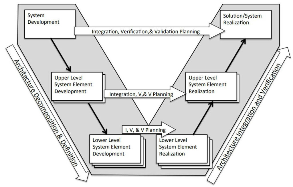
To truly master the Vee Diagram, one must understand its core components and stages. The Vee Diagram is divided into a left side, representing decomposition of requirements and system definition, and a right side, representing integration and recomposition. Understanding each stage in depth is key to leveraging the full power of the Vee Diagram.
Mastering System Engineering V Diagram: Unravelling the Power of the Vee
The System Engineering V Diagram
At the heart of System Engineering is the Vee Model, a diagrammatic representation of the system development lifecycle. It is depicted as a ‘V’ and represents a sequential progression of plans, specifications, and products that are baselined and put under configuration management.
The Vee Model is comprehensive in its scope, covering all system life cycle stages. These stages have been elaborately laid out in the “Generic Life Cycle Stages” table of the highly referenced INCOSE Systems Engineering Handbook (INCOSE 2012).
Understanding the Vee Model
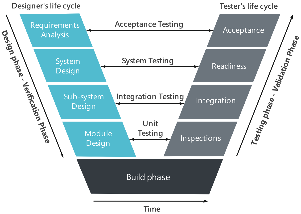
The Vee Model’s distinctive “V” shape represents the sequential stages inherent in a project life cycle. On the left side of the “V”, we see the breakdown of requirements and the creation of system specifications. On the flip side, the right side of the “V” correlates with the unification of components and their subsequent validation.
Guiding the journey from project inception through to completion, the Vee Model offers vital direction. It sketches out the sequence of actions to undertake and the anticipated outcomes throughout the product development process. The primary goal of any project utilising the Vee Model is to accomplish these specific objectives:
- Minimization of Project Risks
- Improvement and Guarantee of Quality
- Reduction of Total Cost over the Entire Project and System Life Cycle
- Improvement of Communication between all Stakeholders
Benefits of the Vee Model
By improving project transparency through standardized approaches, the Vee Model helps with project control. It facilitates early recognition of planning deviations and risks, thus enhancing process management and reducing project risk. Moreover, by ensuring that the results are complete and of desired quality, the Vee Model significantly contributes to quality assurance.
In terms of cost management, applying a standardized process model like the Vee Model makes it possible to calculate, estimate, and control the effort for the development, production, operation, and maintenance of a system in a transparent manner. The results obtained are consistent and can be easily retraced, reducing the acquirers’ dependency on the supplier and the effort for subsequent activities and projects.
Design and Testing in the Vee Model
The Vee model emphasizes a requirements-driven design and testing process. All design elements and acceptance tests are traceable to one or more system requirements, with every requirement addressed by at least one design element and acceptance test. This level of rigor ensures that the implemented system aligns with the stated requirements and that these requirements adequately address the goals identified early in the process.
In essence, the Vee Model provides a structured, standardized, and efficient approach to system engineering. It’s no wonder it’s an indispensable tool for all stakeholders involved in system development, firmly remaining at the forefront of system engineering practices.
Exploring the Left Side of the V Diagram: A Closer Look
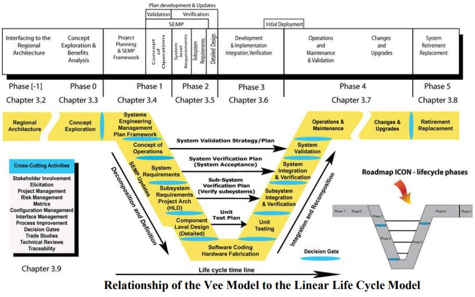
The left side of the systems engineering V Diagram in system engineering is where the foundational work for creating and defining a system takes place. It’s a sequential descent into detail that begins with broad, high-level planning and progressively narrows down into specific, detailed designs and requirements. This section tightly integrates various stages, from defining the system’s architecture to detailing component level designs. Let’s delve into these critical phases to understand how they collectively lay the groundwork for successful system development.
Defining the System’s Architecture
The journey down the left side of the systems engineering V Diagram starts with defining the system’s architecture. This stage is about creating a blueprint for the system that outlines its high-level structure and identifies the primary components and their interactions. The system architecture serves as a framework guiding the development process, ensuring that the system’s design aligns with stakeholders’ needs and operational requirements.
Systems Development
Following the architectural definition, the focus shifts to systems development. This phase builds on the established architecture, diving deeper into how the system will operate and be implemented. Systems development encompasses the formulation of strategies for system integration, identifying technology solutions, and planning for system deployment. This stage ensures the feasibility and practicality of the system’s architectural design.
Concept of Operations (ConOps)
Integral to the left side of the V Diagram is the Concept of Operations (ConOps). The ConOps document describes how the system will be used from the perspective of the end-user. It outlines the system’s operational goals, anticipated scenarios of use, and the context in which the system will operate. The ConOps ensures that the system’s development aligns with its intended use and operational environment.
System-Level Requirements
Progressing further down the left side, we establish the system-level requirements. These requirements capture what the system must do to satisfy stakeholder needs and meet the operational objectives described in the ConOps. The system-level requirements encompass performance parameters, operational capabilities, and interface specifications. This stage translates the conceptual understanding of what the system needs to achieve into quantifiable and verifiable requirements.
Subsystem-Level Requirements
After defining the system-level requirements, the process narrows down to subsystem-level requirements. Each major component or subsystem identified during the architectural design phase is now analyzed to determine its specific requirements. This phase ensures that each subsystem’s functionality and performance align with the overall systems architecture and operational goals.
Component-Level Designs (Detailed)
The final stage on the left side of the V Diagram involves detailed component-level designs. This stage is where the abstract becomes concrete, as engineers create detailed designs and specifications for every component and piece of the subsystems. These detailed designs encompass the nitty-gritty of materials, dimensions, interfaces, and other critical specifications needed for manufacturing and assembly. This comprehensive detailing is essential for the successful realization of the system and serves as a direct input into the right side of the V, where integration and verification take place.
The Cumulative Impact of the Left Side
By meticulously defining and detailing every aspect of the system from architecture to component-level designs, the left side of the V Diagram ensures a solid foundation is in place. This careful planning and specification work supports effective integration, efficient problem-solving, and ultimately the delivery of a system that meets or exceeds all performance, operational, and stakeholder requirements. It’s a testament to the systematic and methodical approach embedded in the very essence of system engineering, emphasizing thoroughness at every step to ensure project success.
Recommended Further Reading Amazon BooksThe right side of the systems engineering V Diagram in system engineering represents the journey from detailed designs to the operational, fully integrated system. This portion of the diagram is where the theoretical and planned aspects of the system, developed meticulously on the left side, are transformed into a tangible, working product. The process begins at the bottom of the V, immediately after detailed component-level designs have been finalized, and ascends through various stages of construction, testing, and integration toward the ultimate goals of system validation, and operations and maintenance. Let’s walk through these essential phases to understand their contributions to system development.
Construction of Product Assembly or Coding
The first step on the ascending right side of the systems engineering V involves turning the detailed designs into physical reality through construction, product assembly, or coding (for software systems). This stage is where raw materials, components, and code come together to form the actual parts of the system. Each component and subsystem is built or coded in accordance with the specifications detailed on the left side of the V. It is a critical phase where the accuracy of the design is first put to the test in real-world application.
Unit Testing
Following construction and assembly, each unit (or the smallest testable parts of a system) undergoes rigorous testing in this phase. Unit testing is meant to verify that each element performs according to its design specifications. It’s a crucial step to catch and rectify any flaws or discrepancies early in the development process before they can escalate into more significant issues. For software components, this typically involves automated tests that run the code under various conditions and inputs.
Subsystem Integration and Verification
After individual units have been tested, the next phase involves integrating these units into subsystems and verifying their collective functionality. This integration process is pivotal since it is where interactions between units are tested. Verification at this stage ensures that the subsystems meet the detailed requirements and specifications outlined on the left side of the V. It may involve a series of tests designed to validate performance, reliability, and compliance with defined interfaces.
System Integration and Verification
Ascending further up the V, subsystems are then integrated to form the complete system. The system integration phase is where the interplay between different subsystems is thoroughly tested, and the system as a whole is verified against the system-level requirements set forth near the beginning of the project. This stage is crucial for ensuring that all components work harmoniously and that the system performs its intended functions within operational parameters.
System Validation
With integration complete, the system validation phase seeks to ensure that the entire system fulfills its intended purpose in the real-world operational environment. Validation activities include testing the system under actual or simulated operating conditions to ensure it meets the needs of the users and other stakeholders identified during the initial phases of the project. This is where the system proves its effectiveness in fulfilling the Concept of Operations (ConOps) outlined at the outset.
Operations and Maintenance
Finally, as we reach the top of the right side of the V, the system transitions into the operations and maintenance phase. This stage marks the beginning of the system’s operational life, where it serves its intended functions and undergoes maintenance activities to ensure sustained performance and longevity. Operations and maintenance involve routine checks, updates, upgrades, and repairs as necessary to adapt to evolving requirements and operational challenges over time.
The Culmination of the Right Side
The ascent of the right side of the V Diagram encapsulates the practical realization and operationalization of the system, built upon the detailed groundwork laid on the left side. It illustrates the systematic approach to bringing complex systems to life, from individual components to an integrated, operational whole. Each phase serves as a critical checkpoint to ensure that the system not only meets its design specifications but also fulfills its destined operational roles. Through this structured process, system engineering effectively bridges the gap between theoretical design and real-world application, ensuring the delivery of functional, reliable, and effective systems.
Recommended Further Reading Amazon BooksThe Steps Behind the System Engineering V Diagram
The Vee Diagram, otherwise known as the V Model, is a process model that can be tailored to fit specific types of programs or enterprises. It’s a dynamic tool that system engineers use to organize and visualize the life cycle of a system from conception to decommission. Now, let’s delve deeper into its structure and how it operates.
- In every box, you’ll find the objectives of the phase.
- For each box on the left leg, apply the 13 systems engineering functions to achieve the objectives.
- Move Down the Left Leg, completing each phase sequentially, then move up the right leg, which is concerned with physical realization (or “implementation”).
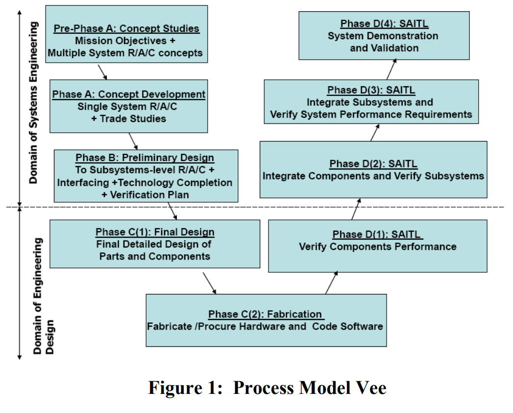
- Pre-Phase A (Concept Studies) – Produce a range of feasible alternatives.
- Phase A (Concept and Technology Development) – Through trade studies, achieve a single system “Architecture” with requirements.
- Phase B (Produce a Preliminary Design) – Establish a preliminary design, with subsystem requirements, interfaces, and resolved technology issues.
- Phase C (Detailed Design) – Create detailed design and drawings, purchase or manufacture parts and components, and code software.
- Phase D (System Assembly, Integration, Test, and Launch) – Assemble subsystems, integrate subsystems to create systems, test for verification and validation of performance, and deploy the system.
- Left Leg: Formulation phases that are concerned with Decomposition and Definition.
- Right Leg: Implementation phases that are concerned with Integration and Verification.
- Decomposition and definition is logically “tearing down” the system to reveal the complete system architectural design.
- Proceeding up the right leg, Integration and Verification equate to “building up” the physical system and testing – from the component level to a completed, functioning, and tested system.
- The Vee chart is divided by a horizontal dashed line that reveals the responsibility boundary between the systems engineering tasks and the tasks performed by the design engineering teams applying the Engineering Design Process (EDP) to create a detailed design of a subsystem.
Understanding the System Engineering V Diagram is a vital step towards mastering system engineering. This versatile model has the power to simplify complex processes and enhance your engineering prowess. So dive in, explore, and watch your proficiency grow.
System Engineering V Diagram Process Life Cycle Stages
Among the several models and diagrams used in system engineering, the Vee model stands out for its simplicity and versatility. Let’s explore the power of the Vee and how it can help streamline your system engineering process.
New projects typically begin with an exploratory research phase which generally includes the activities of concept definition, specifically the topics of business or mission analysis and the understanding of stakeholder needs and requirements. These mature as the project goes from the exploratory stage to the concept stage to the development stage.
- Exploratory Stage: This is where the project begins. At this stage, the focus is on understanding the business or mission and defining the concept based on stakeholder needs and requirements.
- Concept Stage: This stage sees the maturation of the project as it moves from exploration to development. The concept is clarified and refined.
- Development Stage: The project further matures at this stage. The system starts to take shape based on the defined concept.
The production phase includes the activities of system definition and system realization, as well as the development of the system requirements and architecture through verification and validation.
- System Definition: This involves the detailing of the system requirements and architecture.
- System Realization: This is the practical application of the system definition, bringing the system to life.
- Verification and Validation: This involves ensuring that the system meets the defined requirements and achieves its intended purpose.
The utilization phase includes the activities of system deployment and system operation. The support phase includes the activities of system maintenance, logistics, and product and service life management, which may include activities such as service life extension or capability updates, upgrades, and modernization. The retirement phase includes the activities of disposal and retirement, though in some models, activities such as service life extension or capability updates, upgrades, and modernization are grouped into the “retirement” phase.
Recommended Future Learn Short CoursesFrequently Asked Questions: System Engineering V Diagram
We’ve compiled a list of frequently asked questions to help you unravel the potency of the V Diagram in System Engineering. These questions comprise the most common queries regarding the application of the Systems Engineering practice in product development.
1. How does acknowledging the level of team knowledge and skill improve the product development process?
Recognizing the team’s current knowledge and skills allows for an effective product development process selection. It enables a more targeted approach to skill enhancement, ensuring that the team can handle the complexity of the project. This awareness also aids in the initial increase of the team’s skills and knowledge, paving the way for a smoother product development journey.
2. Why should project plans expressly include iterations?
As Scheithauer states, “iterations are the rule in systems engineering, not the exceptions”. Hence, it’s vital to create plans that explicitly incorporate iterations, like the prototype stage, to account for adjustments and improvements over the project’s lifecycle. This approach fosters a more dynamic and adaptable development process.
3. What’s the benefit of decomposing the project using the Basic-V framework?
Utilizing the Basic-V framework to deconstruct a project actively encourages the development team to deliberate on the necessary work products and their testing requirements. It ensures that the developed system has adequate performance and meets the required standards. This method can significantly reduce the likelihood of overlooked elements and enhance the overall quality of the project.
4. Why are modeling and communications important in systems designs?
Modeling and effective communication are crucial for a successful project. Modeling can help avoid rework cycles by ensuring all systems are adequately integrated and functional. On the other hand, regular discussions surrounding defined work products can improve team communication, fostering a more collaborative and productive work environment.
5. How can meaningful metrics improve project progress tracking?
Instead of sticking to a fixed development plan, written with limited knowledge at the project’s outset, implementing meaningful metrics can provide a more accurate measure of progress. This approach allows for dynamic project plan updates throughout the project’s lifespan, leading to more informed decision-making and improved project outcomes.
6. How does the Knowledge Growth Curve aid in product development?
The Knowledge Growth Curve provides a visual representation of the team’s skills and knowledge. It helps identify where initial skills can be improved and how to increase them during development. By understanding this curve, teams can focus on growth areas, leading to a more efficient and successful product development process.
7. What is the role of the Development-V and Assurance-V in system engineering?
The Development-V and Assurance-V help teams to map out necessary work products and ensure they are tested sufficiently. These models force the development team to consider what outputs are needed, and how to verify the developed system has adequate performance, providing a robust framework for product development.
8. How can system engineering improve communication among sub-teams?
System engineering encourages the use of defined work products and active weekly discussions surrounding these products. This approach can enhance communication between sub-teams, leading to more coordinated efforts and a more cohesive final product.
9. How does modeling aid in system integration?
Modeling provides a detailed representation of system designs, helping teams identify potential issues before integration. By using modeling throughout all systems, teams can avoid rework cycles and ensure all components are adequately integrated and functional, leading to a more efficient development process and a higher-quality end product.
Conclusion
In conclusion, the power of the Vee in system engineering is undeniable. Mastering the System Engineering V Diagram equips you with an unparalleled understanding of the system’s life cycle, affording you the capability to plan, track, and control system development with a meticulous attention to detail.
Grasping the Vee model’s sequential and iterative processes enables you to ensure that all system requirements are identified, considered, and tested, thus facilitating the delivery of high-quality, reliable, and effective systems. It’s no surprise that system engineers and project managers around the world rely on this powerful tool.
Why System Engineering V Diagram?
- The Vee model provides a structured and systematic approach to system development.
- It aids in the mitigation of project risks by ensuring thorough requirements management and traceability.
- The model’s inherent feedback loops facilitate continuous improvement and adaptation to changes.
Key Takeaways
- The System Engineering V Diagram is a comprehensive tool for managing system development from inception to decommissioning.
- Its cyclical nature encourages continuous improvement and adaptation, making it a dynamic and flexible tool.
- Mastering the Vee model can significantly enhance your abilities as a system engineer or project manager, leading to more successful and efficient projects.
The world of system engineering is vast and complex, but tools like the System Engineering V Diagram allow us to navigate it with expertise and confidence. By mastering the Vee, you open the door to new levels of understanding and control over your projects, positioning you for success in this exciting field. Want to know more? Check out our Top 10 Short Courses review for Systems Engineering.
Remember, the journey to mastery is a process. Stay committed, stay curious, and embrace the power of the Vee in system engineering.
Sources
- Sutherland, Joshua; Kamiyama, Haruya; Aoyama, Kazuhiro; Oizumi, Kazuya. “Systems Engineering and the V-Model: Lessons from an Autonomous Solar Powered Hydrofoil.”
- Systems Engineering Department. “Systems Engineering Guide: System Life Cycle Process Models – Vee Diagram.”
- International Council on Systems Engineering (INCOSE). “Systems Engineering Handbook: A Guide for System Life Cycle Processes and Activities, version 3.2.2.”
- International Organization for Standardization (ISO)/International Electrotechnical Commission (IEC). “Systems and Software Engineering, Part 1: Guide for Life Cycle Management.”
- International Organization for Standardization (ISO)/International Electrotechnical Commission (IEC). “Systems and Software Engineering — System Life Cycle Processes.”
- International Organization for Standardization (ISO)/International Electrotechnical Commission (IEC). “Systems Engineering — A Guide for The Application of ISO/IEC 15288 System Life Cycle Processes.”
- The National Academies (USA). “Pre-Milestone A and Early-Phase Systems Engineering.”








Remarkable things here. I’m very gload to look your post.
Thanks a lot and I’m takinng a look forward to touch you.
Will yyou kidly drop me a e-mail?