The object-oriented systems engineering method (OOSEM), also known as object-oriented systems engineering (OOSE), is a unique and innovative approach to system-level development. Devised by the Object Management Group (OMG), it ingeniously combines object-oriented concepts with traditional systems engineering practices. The original concepts utilised in object-oriented software development are applied to systems engineering, enhancing its efficiency and effectiveness.
In this blog post, we’ll start by revisiting the basic concepts of OOSEM. We’ll then draw comparisons between OOSEM and the more traditional structured analysis approaches to model-based systems engineering (MBSE). We’ll delve into how OOSEM is implemented, explore the key features of an object-oriented methodology, and conclude by examining the International Council on Systems Engineering (INCOSE)’s perspective on OOSEM.
Table of Contents
- Differentiating MBSE Modelling Languages
- Understanding UML and SysML in OOSEM
- Comparing OOSEM with Structured Approach
- OOSEM features
- OOSEM processes
- Defining the Problem
- Frequently Asked Questions
- Why is problem identification crucial in both OOSEM and MBSE implementations?
- How can a systematic approach improve problem definition in OOSEM?
- Why is stakeholder identification important in OOSEM and MBSE?
- How does the product lifecycle impact the systems engineering process?
- How do standards, regulations, and policies affect the systems engineering process?
- INCOSE and OOSEM Definition
- Conculsion
- References
Differentiating MBSE Modelling Languages
MBSE can be implemented using a plethora of modelling languages, each with their unique differentiating factors. These differences can be based on whether the information is expressed visually or textually, or whether the paradigms used to group the information are object-oriented, functional, or otherwise.
Visual languages are often the preferred choice for modelling due to their readability and accessibility to diverse stakeholders. Object-oriented languages hold a special place in systems engineering because they can be effortlessly applied to systems that can be broken down into sets of objects. The resulting model incorporates functions for needs and requirements analysis, logical and allocated architecture design, and validation and verification. The Unified Modelling Language (UML), and Systems Modelling Language (SysML), both products of OMG, are commonly used for OOSEM.
Understanding UML and SysML in OOSEM
UML was originally developed for software engineering, while SysML is an adaptation of UML specifically optimised for use in MBSE. SysML is a graphical language that employs diagrams and tables to express system information and provide a framework for representing system structure, behaviour, and requirements.
Before the advent of OOSEM, systems engineering was largely dependent on structured analysis to scrutinise needs, identify features, and develop a system model. OOSEM, like structured analysis, is used to define a system model but employs a fundamentally different approach.
Comparing OOSEM with Structured Approach
The structured approach kicks off with a functional analysis where functions are defined as data transformations that operate on data inputs to produce the required outputs. Post sufficient decomposition and specification of the required system behaviour, these functions are further defined as system elements or components, paving the way for physical modelling of the system. The classic ‘V diagram’ is often used to visualise the structured analysis approach to MBSE.
Like its structured counterpart, OOSEM is iterative in nature. However, it starts with the analysis of objects that constitute the system architecture and then moves on to allocate the functions to these objects to fulfil specific needs. In subsequent design iterations in OOSEM, each object is further decomposed into sub-components to perform sub-functions. This cycle continues until the system functionality is adequately granular to enable requirements development, ultimately leading to the system specification.
OOSEM features
Systems engineering is a complex process, and the use of object-oriented systems engineering (OOSEM) in Model-Based Systems Engineering (MBSE) significantly streamlines this process. OOSEM combines elements from structured analysis with object-oriented concepts, employing a range of modelling techniques throughout the lifecycle of a system. The process begins with the separation of concerns to manage complexity, which is then followed by integrating these concerns to create a cohesive system model. There are four key features of OOSEM within the context of MBSE:
1. Abstraction
This allows designers to separate the functionality of a component from its physical implementation. The use of logical representations of components aids in identifying functionality and attributes that are common across the system. By removing the constraints of physical representations, a clearer understanding of component functionality and the interaction between various components at a logical level is achieved.
2. Encapsulation
Encapsulation is used to define the boundaries of objects and their interaction with other elements of the system. Functions are encapsulated within the object and are not visible to other components. Interaction between various components occurs through defined interfaces, independent of internal functions. The benefit of encapsulation is that it allows for the replacement of components with others that produce the same functional outputs and have the same interfaces. This promotes modularity and reduces or eliminates interdependency between components.
3. Inheritance
Thirdly, inheritance allows one component to inherit the functionality and interfaces of another component. This is not limited to objects and functions. Within OOSEM, inheritance is utilised when creating a representation of a physical component. A newly created physical component can inherit the properties of an existing logical component. The designer can then add additional functionalities and/or interfaces for that specific instance of the physical component. A single component, known as a child component, can inherit properties from more than one source component, known as parent components, to support complex designs.
4. Object Reuse
Finally, object reuse is a powerful tool for designers and is closely related to inheritance. For instance, if several child components perform largely similar functions, they can all inherit from a common parent or several common parents. The designer can then modify their core functionalities for each use case. Object reuse enhances the efficiency of the process and accelerates the completion time of the project.
In conclusion, OOSEM within MBSE provides a structured approach to managing the complexity of systems engineering, promoting efficiency and reducing interdependencies between components. These four key features of OOSEM provide a robust framework for systems engineering, promoting efficient design and reducing time to project completion.
OOSEM processes
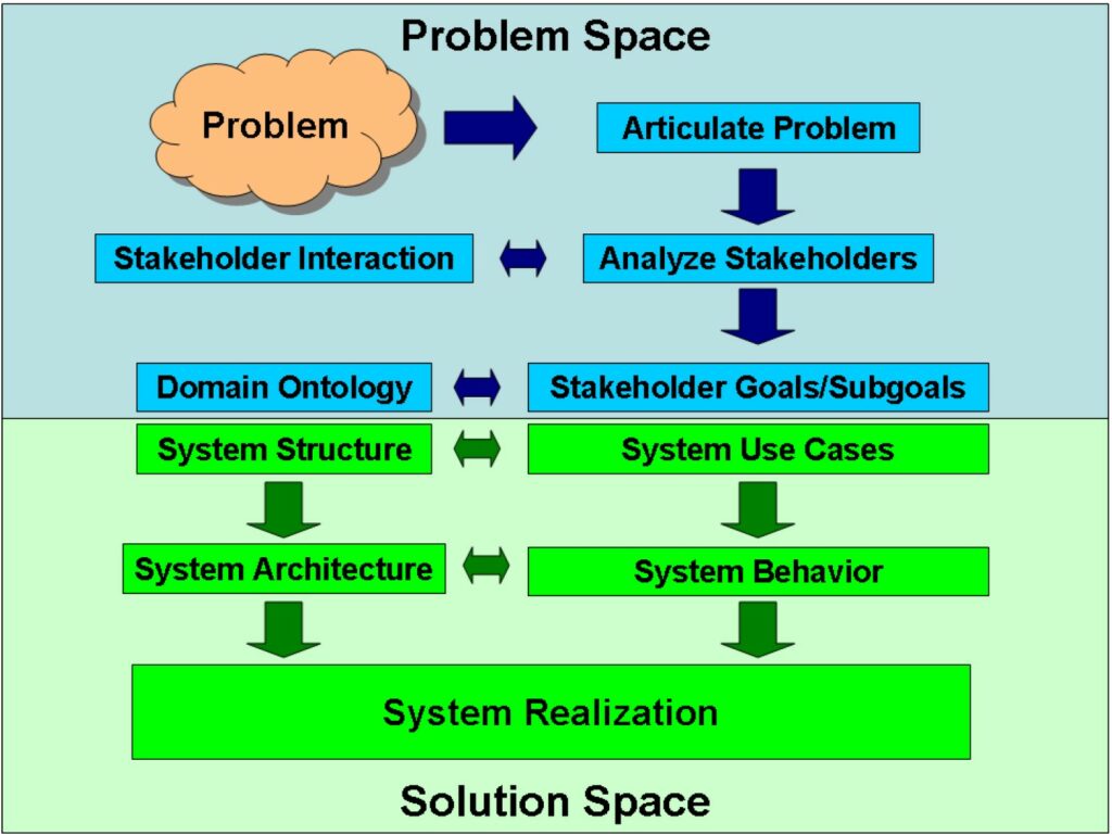
The OOSEM procedure is comprised of multiple stages that commence from a broad level of abstraction and progressively delve into more detailed system descriptions. It is commonplace to traverse the final four stages multiple times before reaching an optimal solution.
- The first stage is the Definition of Requirements. This phase involves identifying the problem that the system is designed to solve and defining the necessary functionalities. Factors such as use cases, operational limitations and environments, among others, may be considered. This stage culminates in a requirements specification for the system. As we shall explore in the ‘What’s the Problem’ section, this is a pivotal step. Inadequate execution at this stage could lead to the failure of the entire MBSE process.
- The second stage is Requirements Analysis. This phase commences with a broad description of the required objects, their functionalities, and the logical connections between them. Various tools may be utilised during this process, including class diagrams, sequence diagrams, state diagrams, and collaboration diagrams.
- The third stage is System Design. This phase initiates with the integration of the objects into a digital twin and proceeds to the design of the physical system elements and infrastructure. This stage encompasses the virtual verification and validation of the design using the digital twin.
- The fourth stage is Implementation. This phase results in a physical prototype of various subsystems derived from the digital twin. These are then subjected to functional verification and validation tests. Sometimes, after several iterations, this stage extends to increasingly higher levels of system integration.
- The final stage is Testing. This phase provides verification and validation of the completed system and its operation as specified by the design requirements.
Defining the Problem
What questions should be asked to ensure a structured approach to problem definition?
To ensure a structured approach to problem definition and stakeholder identification, consider the following questions:
- What is the system’s context of use and who or what interacts with it?
- Who experiences the problem(s) that need to be solved?
- Who possesses the knowledge to offer a solution?
- What groups are involved throughout the product lifecycle?
- What are the operational scenarios and conditions?
- Who will fund the system, and are they users of it?
- What standards, regulations, and policies must be taken into account?
Frequently Asked Questions
Why is problem identification crucial in both OOSEM and MBSE implementations?
Identifying the problem to be solved is a fundamental step in both Object-Oriented Systems Engineering Method (OOSEM) and Model-Based Systems Engineering (MBSE). Without a well-defined and detailed problem statement, the systems engineering process can encounter numerous challenges and setbacks.
How can a systematic approach improve problem definition in OOSEM?
In OOSEM, a systematic approach to problem definition can be established by identifying all the stakeholders. This approach ensures a comprehensive understanding of the needed system performance. System failure can occur if one or more key stakeholders are overlooked.
Why is stakeholder identification important in OOSEM and MBSE?
Inclusion of all stakeholders leads to a comprehensive understanding of the system performance requirements. Missing out on any key stakeholders could potentially result in system failure. Therefore, a systematic and structured approach to problem definition and stakeholder identification is critical.
How does the product lifecycle impact the systems engineering process?
The product lifecycle plays a significant role in the systems engineering process. Understanding the groups involved throughout this lifecycle can provide valuable insights into the problem to be solved and the potential solutions.
How do standards, regulations, and policies affect the systems engineering process?
Standards, regulations, and policies play a crucial role in shaping the systems engineering process. They establish the guidelines for system design, use, and maintenance, and must be considered during the problem definition and solution identification stages.
Recommended Further Reading Amazon BooksINCOSE and OOSEM Definition
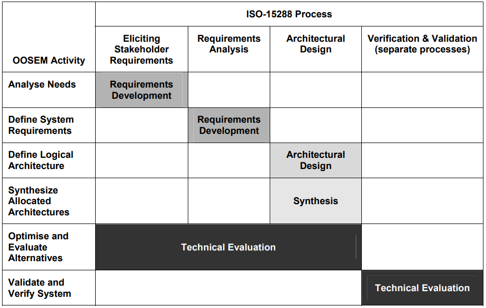
In the context of INCOSE’s definition, both MBSE and OOSEM are obligated to bolster the definition of system requirements, system design, system analysis, and system verification and validation. These foundational activities encompass the following elements (as depicted in Figure 3):
Firstly, there’s the coordination and execution of system architecture and design, with a focus on defining the interconnections between various system development activities.
Secondly, implementation is carried out based on SysML, a graphical modelling language in software and systems engineering that supports the specification, analysis, design, verification and validation of a broad range of systems and systems-of-systems.
Thirdly, system performance analysis is conducted using parametric diagrams. These diagrams are amalgamated with weighting factors and value measures to derive optimal configurations.
Fourthly, external modelling and simulation are optional components within this framework.
Lastly, system testing, validation, and verification are distinct processes that operate independently from the primary development activities. These processes are crucial to ensure that the system performs as expected and meets the requirements set out in the initial stages.
In conclusion, object-oriented systems engineering (OOSEM) and model-based systems engineering (MBSE) are intrinsically linked, with OOSEM serving as a methodology within the broader MBSE approach. Both methodologies share a common goal: to streamline and improve the systems engineering process.
Conculsion
In essence, Object-Oriented Systems Engineering Methodology (OOSEM) is a Model-Based Systems Engineering (MBSE) strategy, developed by the Object Management Group (OMG). This unique approach marries traditional systems engineering practices with object-oriented concepts. Typically, it is executed using Systems Modelling Language (SysML) and unfolds in a sequence of stages. These stages encompass defining requirements, analysing these requirements, designing the system, implementing the system, validating it, and verifying its performance.
A comprehensive understanding of the issue(s) to be addressed, leading to a detailed definition of the requirements, is a crucial prerequisite to the successful execution of an OOSEM project. Moreover, the International Council on Systems Engineering (INCOSE) has pinpointed key OOSEM development activities along with common sub-activities.
Read our article on Unlocking MBSE: Choosing the Best Books for Model-Based Systems Engineering.
References
Exploring the Application of Object Oriented Systems Engineering in Complex Systems, Presented by IEEE International Systems Conference
Understanding the Object-Oriented Systems Engineering Method, Provided by INCOSE
Embracing an Object-Oriented Development Approach, A Guide by Oracle


