
Table of Contents
- 1. Why Systems Architecture Matters: The Foundation of Success
- 2. Understanding the System Lifecycle Context
- 3. The INCOSE Standards Foundation
- 4. Step-by-Step Architecture Definition Process
- 5. Model-Based Systems Engineering (MBSE) Implementation
- 6. Architecture Views and Documentation
- 7. Validation and Verification
- 8. Managing System Levels and Hierarchy
- 9. Continuous Architecture Evolution
- 10. Common Pitfalls and How to Avoid Them
- 11. Success Factors and Best Practices
- 12. Conclusion: Building Architecture Excellence
1. Why Systems Architecture Matters: The Foundation of Success
Imagine building a skyscraper without architectural plans, or conducting an orchestra without a musical score. The result would be chaos, inefficiency, and likely failure. Systems architecture design defines system behavior and structure characteristics in accordance with derived requirements. The architecture ensures that the system elements operate together in the applicable operating environment to satisfy Stakeholder needs.
In today’s complex technological landscape, systems are becoming increasingly intricate, involving multiple stakeholders, diverse technologies, and evolving requirements. Without a systematic approach to architecture definition, organizations face:
- Cost overruns and schedule delays due to rework and design defects discovered late
- Misaligned stakeholder expectations leading to systems that don’t meet actual needs
- Poor integration between system components and external interfaces
- Difficulty managing change throughout the system lifecycle
- Limited reusability and scalability for future projects
Systems Engineering is all about trying to manage the system through its entire lifecycle and to manage all the relevant relationships to other related systems. By following a structured approach to systems architecture definition, you create an authoritative foundation that guides all subsequent development activities while ensuring stakeholder needs are met efficiently and effectively.
Recommended Further Reading Amazon Books


2. Understanding the System Lifecycle Context
Before diving into architecture definition, it’s crucial to understand where architecture fits in the broader system lifecycle. The INCOSE Systems Engineering Handbook defines 6 generic lifecycle stages through which a system evolves: Concept, Development, Production, Utilization, Support, and Retirement.
Architecture definition primarily occurs during the Concept and early Development phases, but its impact spans the entire lifecycle:
- Concept Phase: Initial architecture concepts support feasibility studies and early requirements definition
- Development Phase: Detailed architecture definition guides design, implementation, and integration
- Production Phase: Architecture provides the blueprint for manufacturing and quality assurance
- Utilization Phase: Architecture enables effective operation and performance monitoring
- Support Phase: Architecture facilitates maintenance, upgrades, and problem resolution
- Retirement Phase: Architecture guides decommissioning and technology transition
Understanding this lifecycle context helps you make architecture decisions that optimize not just immediate development needs, but long-term sustainability and evolution.
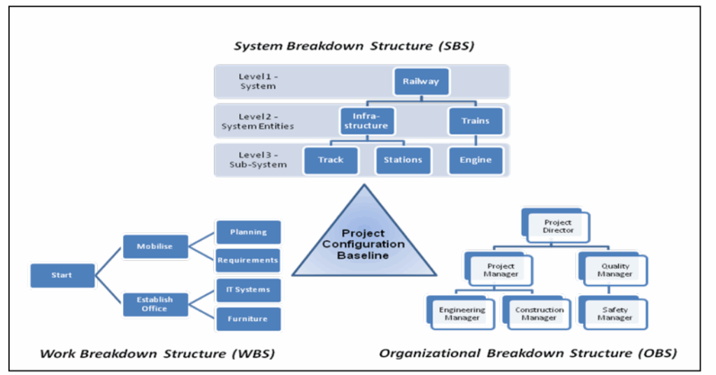
Structures Source: INCOSE
3. The INCOSE Standards Foundation
ISO/IEC/IEEE 15288:2015 establishes a common framework of process descriptions for describing the life cycle of systems created by humans. The standard defines specific processes that provide the foundation for systematic architecture definition:
Key INCOSE/ISO 15288 Processes for Architecture:
1. Stakeholder Needs and Requirements Definition
- Identify and engage all relevant stakeholders
- Elicit, analyze, and document stakeholder needs
- Transform needs into measurable requirements
2. System Requirements Definition
- Derive system requirements from stakeholder needs
- Establish requirement priorities and constraints
- Define verification and validation criteria
3. Architecture Definition
- The Architecture Definition process makes a state change in the abstract definition of system elements
- Synthesize architecture alternatives
- Evaluate and select preferred architecture
- Document architectural decisions and rationale
4. Design Definition
- The Design Definition process makes a state change from that abstract definition to a concrete definition
- Elaborate architecture into detailed design specifications
- Define implementation-specific elements
This progression from stakeholder needs through requirements to architecture and design provides a traceable path that ensures the final system meets its intended purpose.
System Architecture Framework (SAF) – Key Steps Summary Tables
The System Architecture Framework (SAF) provides a structured approach to defining systems architecture through four interconnected domains. This comprehensive methodology guides teams from initial operational understanding through to physical implementation, ensuring stakeholder needs are systematically translated into robust technical solutions.
The following tables break down the SAF methodology into actionable steps, clearly defining what needs to be accomplished at each stage and what outcomes to expect. Each step builds upon the previous ones, creating a coherent path from operational scenarios to implementable architecture.
| Domain | Step | Key Objectives |
|---|---|---|
| Operational Domain (SOV) | SOV01: Operational Scenario View |
|
| Operational Stakeholder Identification |
| |
| SOV04: Operational Interaction |
| |
| Functional Domain (SFV) | SFV01: System Use Case |
|
| SFV04: Functional Interaction |
| |
| Logical Domain (SLV) | SLV01: System Context |
|
| Logical Architecture Development |
| |
| Physical Domain (SPV) | Physical Architecture Mapping |
|
| Cross-Domain Activities | Requirements Traceability |
|
| Architecture Validation |
| |
| Documentation and Communication |
|
4. Step-by-Step Architecture Definition Process
Phase 1: Operational Domain (SOV) – Understanding the “Why”
Step 1.1: Develop Operational Scenarios
Begin by creating compelling narratives that describe how your system will be used in real-world contexts.
How to do it:
- Conduct stakeholder workshops to gather operational stories
- Create “A Day in the Life” scenarios that illustrate typical system usage
- Document use cases in narrative form using stakeholder language
- Include both normal and exceptional scenarios (e.g., system failures, edge cases)
Example Structure:
Scenario: [Name]
Description: [2-3 paragraph narrative describing the operational context]
Key Stakeholders: [List of involved parties]
Trigger Events: [What initiates this scenario]
Success Criteria: [How stakeholders will know the scenario succeeded]
Practical Tip: Use storytelling techniques to make scenarios engaging and memorable. This helps build stakeholder buy-in and ensures everyone shares the same vision.
Step 1.2: Identify and Analyze Stakeholders
Requirement gathering is where the project starts taking shape. This involves interviewing stakeholders, observing end-users, and sometimes conducting surveys to gather both explicit requirements (directly expressed by stakeholders) and implicit requirements (needs not always verbalized but essential for)
Systematic Stakeholder Identification Process:
- Primary Stakeholders: Those who directly interact with or benefit from the system
- End users, operators, customers
- Secondary Stakeholders: Those affected by or influencing the system
- Regulators, maintainers, suppliers
- Key Players: Those with decision-making authority
- Sponsors, project managers, technical authorities
Stakeholder Analysis Template:
Stakeholder: [Name/Role]
Interest Level: [High/Medium/Low]
Influence Level: [High/Medium/Low]
Key Concerns: [Primary interests and concerns]
Success Criteria: [How they define project success]
Communication Preferences: [How they prefer to receive updates]
Step 1.3: Model Operational Interactions
Transform your scenarios into structured interaction models using sequence diagrams.
Steps:
- Select key scenarios for detailed modeling
- Identify participating entities (people, organizations, external systems)
- Map the sequence of interactions using timeline-based diagrams
- Document information exchanged at each interaction point
- Note timing constraints and dependencies
This step reveals the dynamic behavior of your system in its operational context and helps identify critical interfaces.
Phase 2: Functional Domain (SFV) – Defining the “What”
Step 2.1: Derive System Use Cases
Requirements analysis (a.k.a. preliminary design) involves understanding the problem; what is needed.
Transform operational scenarios into system-level use cases that focus on what the system must do.
Use Case Definition Process:
- Extract system functions from operational interactions
- Define system boundaries – what’s inside vs. outside your system
- Identify actors – external entities that interact with your system
- Document use case descriptions with:
- Preconditions
- Main flow of events
- Alternative flows
- Postconditions
- Exception handling
Use Case Template:
Use Case: [Name]
Primary Actor: [Who initiates this use case]
Goal: [What the actor wants to achieve]
Preconditions: [System state before use case starts]
Main Success Scenario: [Step-by-step normal flow]
Extensions: [Alternative flows and exception handling]
Postconditions: [System state after successful completion]
Step 2.2: Define Functional Requirements
Break down each use case into specific functional requirements that define system capabilities.
Requirements Categories:
- Functional Requirements: What the system must do
- Performance Requirements: How well it must do it
- Interface Requirements: How it connects with external entities
- Constraint Requirements: Limitations and restrictions
Requirements Writing Guidelines:
- Use clear, unambiguous language
- Make requirements testable and verifiable
- Include acceptance criteria
- Assign priority levels (Must have, Should have, Could have)
- Ensure traceability to stakeholder needs
Step 2.3: Model Functional Interactions
Create activity diagrams and sequence diagrams that show how system functions work together.
Activity Modeling Steps:
- Decompose high-level functions into sub-functions
- Define input/output relationships between functions
- Show decision points and alternative paths
- Identify interfaces between functions
- Document timing and sequencing constraints


Phase 3: Logical Domain (SLV) – Organizing the “How”
Step 3.1: Define System Context
The system design model provides an Authoritative Source of Truth [ASoT] digital repository of the project technical baseline including requirement, functional, logical, and physical design representations for each system, subsystem, and component design abstraction level.
System Context Definition Process:
- Draw system boundary – clearly delineate what’s inside your system
- Identify external entities – systems, actors, and environment elements that interact with your system
- Define interfaces – data, energy, material, and information flows
- Document interface specifications – protocols, formats, timing
- Specify environmental conditions – operating environment constraints
Context Diagram Elements:
- System of Interest (your system)
- External systems and actors
- Interface connections with labels
- System boundary clearly marked
Step 3.2: Develop Logical Architecture
Create a technology-independent model that organizes system functions into logical components.
Logical Architecture Process:
- Group related functions into logical components
- Define component interfaces and interactions
- Establish hierarchy levels (system, subsystem, component)
- Allocate requirements to logical components
- Document design rationale for architectural decisions
Key Principles:
- Separation of Concerns: Each component has a clear, distinct purpose
- Cohesion: Related functions are grouped together
- Loose Coupling: Minimize dependencies between components
- Interface Standardization: Use consistent interface patterns
Step 3.3: Define Interface Architecture
Specify how system components communicate and share information.
Interface Definition Steps:
- Identify all component interfaces
- Classify interface types (data, control, user, external)
- Define interface protocols and data formats
- Specify timing and performance requirements
- Document interface control documents (ICDs)
Phase 4: Physical Domain (SPV) – Implementing the Solution
Step 4.1: Technology Selection and Constraints
Transform logical architecture into implementable physical components.
Technology Selection Process:
- Assess technology options for each logical component
- Evaluate against requirements (performance, cost, risk)
- Consider technology constraints (existing systems, standards)
- Make technology decisions with documented rationale
- Update architecture with technology-specific details
Step 4.2: Physical Architecture Definition
Physical configuration items provide a design implementation for the corresponding logical element including the required property attributes and functional operations.
Physical Architecture Activities:
- Map logical components to physical elements (hardware, software, people, facilities)
- Define deployment architecture – where components are located
- Specify physical interfaces – cables, networks, protocols
- Document implementation constraints and dependencies
- Plan integration and testing approach
5. Model-Based Systems Engineering (MBSE) Implementation
Step 5.1: Choose Your Modeling Approach
SysML provides industry standard graphical and textual notations with formal semantics to define system design requirements, behavior and structure characteristics with traceability to the associated requirements.
MBSE Benefits:
- Single Source of Truth: Centralized, authoritative model
- Automated Consistency Checking: Reduce human error
- Impact Analysis: Understand change implications
- Simulation Capabilities: Verify design before implementation
- Automated Documentation: Generate views and reports
Tool Selection Criteria:
- SysML/UML compliance and support
- Integration with other engineering tools
- Model simulation and analysis capabilities
- Team collaboration features
- Scalability for project size
Step 5.2: Create the Digital Architecture Model
Model Organization Structure:
- Project Overview Package: Scope, boundaries, glossary
- Requirements Package: Stakeholder needs and system requirements
- Functional Package: Use cases, activities, interactions
- Logical Package: System context, logical components, interfaces
- Physical Package: Physical components, deployment, implementation
Modeling Best Practices:
- Use consistent naming conventions
- Maintain traceability links between model elements
- Regular model validation and verification
- Version control and configuration management
- Document modeling assumptions and decisions
Step 5.3: Enable Simulation and Analysis
Digital threads are analytical frameworks providing end-to-end system simulation representations to evaluate key performance parameters in virtual environments by exchanging information between different modeling tools across the lifecycle.
Simulation Capabilities:
- Functional Simulation: Verify behavior against requirements
- Performance Analysis: Evaluate timing, throughput, capacity
- Interface Testing: Validate component interactions
- Scenario Analysis: Test different operational conditions
6. Architecture Views and Documentation
Step 6.1: Define Stakeholder-Specific Views
Different stakeholders need different perspectives on the architecture.
Common Architecture Views:
- Operational View: How the system supports business operations
- Functional View: What capabilities the system provides
- Logical View: How the system is organized conceptually
- Physical View: How the system is implemented and deployed
- Data View: What information the system manages
- Interface View: How the system connects to its environment
Step 6.2: Create Architecture Documentation
Documentation Packages:
- Architecture Overview: Executive summary and key decisions
- Requirements Traceability: Links from needs through implementation
- Interface Control Documents: Detailed interface specifications
- Design Rationale: Reasoning behind architectural choices
- Architecture Compliance: Guidelines and constraints for implementation


7. Validation and Verification
Step 7.1: Architecture Validation
Ensure your architecture will meet stakeholder needs.
Validation Activities:
- Stakeholder reviews and feedback sessions
- Scenario walk-throughs using the architecture
- Trade study results validation
- Risk assessment and mitigation planning
Step 7.2: Architecture Verification
Confirm your architecture satisfies specified requirements.
Verification Methods:
- Requirements traceability analysis
- Interface compatibility checking
- Performance analysis against requirements
- Design rule compliance verification
8. Managing System Levels and Hierarchy
Systems exist at multiple levels of abstraction. Your architecture approach must address this hierarchy:
System Level Considerations:
- System-of-Systems: Multiple independent systems working together
- System Level: The primary system being developed
- Subsystem Level: Major functional groupings within the system
- Component Level: Individual implementable elements
Hierarchy Management:
- Define level boundaries clearly
- Establish interface requirements between levels
- Allocate requirements down the hierarchy
- Verify integration up the hierarchy
- Maintain consistency across all levels
9. Continuous Architecture Evolution
Architecture is not a one-time activity but evolves throughout the system lifecycle.
Step 9.1: Architecture Change Management
Change Control Process:
- Identify need for change (requirements evolution, technology updates)
- Assess impact across all architecture domains
- Evaluate alternatives and trade-offs
- Make informed decisions with stakeholder input
- Update architecture and communicate changes
Step 9.2: Architecture Governance
Governance Framework:
- Regular architecture review boards
- Compliance checking against standards
- Performance monitoring against architecture intent
- Lessons learned capture and sharing
10. Common Pitfalls and How to Avoid Them
Architecture Definition Challenges:
- Starting Too Detailed Too Early
- Problem: Jumping to physical solutions before understanding needs
- Solution: Follow the domain progression (Operational → Functional → Logical → Physical)
- Insufficient Stakeholder Engagement
- Problem: Architecture that doesn’t meet real stakeholder needs
- Solution: Continuous stakeholder involvement and validation
- Poor Requirements Traceability
- Problem: Losing connection between needs and implementation
- Solution: Maintain explicit traceability links throughout the process
- Technology-Driven Architecture
- Problem: Choosing solutions before understanding problems
- Solution: Keep technology decisions in the Physical domain, after logical architecture is stable
- Inadequate Interface Definition
- Problem: Integration problems and compatibility issues
- Solution: Define interfaces explicitly with formal interface control documents
11. Success Factors and Best Practices
Critical Success Factors:
- Executive Support: Ensure leadership understands and supports the architecture process
- Cross-Functional Teams: Include all relevant disciplines and stakeholders
- Iterative Refinement: Continuously improve architecture based on feedback
- Tool Integration: Use compatible tools that support collaboration
- Change Management: Plan for and manage architecture evolution
Best Practices:
- Start with stakeholder needs, not technology solutions
- Maintain multiple levels of abstraction simultaneously
- Use visual modeling to improve communication
- Validate architecture through simulation and analysis
- Document decisions and rationale for future reference
12. Conclusion: Building Architecture Excellence
Defining systems architecture is both an art and a science. By following this systematic approach, you create architectures that:
- Meet stakeholder needs through careful requirements analysis
- Optimize across the lifecycle by considering long-term implications
- Enable effective implementation through clear design guidance
- Support evolution and growth through modular, flexible structures
- Reduce project risk through early validation and verification
Your Next Steps:
- Assess your current architecture practices against this framework
- Identify improvement opportunities in your organization
- Plan pilot projects to try these approaches
- Build organizational capability through training and mentoring
- Establish architecture governance to sustain improvements
Remember: great architecture is not about perfect initial designs, but about creating robust frameworks that can evolve and adapt as understanding grows and requirements change. Start with stakeholder needs, build systematically through the domains, and maintain focus on the ultimate goal of delivering value to your users and organization.
The investment in systematic architecture definition pays dividends throughout the system lifecycle, resulting in better systems delivered more efficiently with fewer surprises and greater stakeholder satisfaction.