Drawing System Architecture: Visual & AI-Native Update to Reqi
A look at the new system architecture canvas, the requirements drill-down, and the AI tools that have been quietly built around an INCOSE backbone.
Table of Contents
- What the Visual Architecture Update Adds
- Why this update matters
- 1. The Systems Diagram: a canvas for system architecture
- 2. The Requirements Diagram: a system, its requirements, and the room to add more
- 3. AI requirement elicitation: an INCOSE procedure in a prompt
- 4. AI system allocation: lowest-level capable, every time
- 5. Stitching it together: how the four pieces compose
- What’s next
What the Visual Architecture Update Adds
| Capability | What it means for you |
|---|---|
| AI-native diagramming | Describe the system and let reqi draft the architecture |
| Connected to requirements | Diagrams link to the requirements behind them, not standalone pictures |
| Faster iteration | Change the model and the views keep up |
| Lower barrier | Build architecture without wrestling a heavyweight tool |
Why this update matters
Most requirements tools are tables. They’re great at storing the what, terrible at showing the why — the architecture the requirements live in, the system breakdown they’re meant to satisfy, the relationships between them. Systems engineering, by contrast, is a discipline of structure: stakeholder needs decompose into requirements, requirements allocate to systems, systems decompose into subsystems, all the way down.
This update closes the gap between the spreadsheet view and the engineering view. Reqi now has:
- A graphical system architecture canvas — draw your system breakdown the way you’d draw it on a whiteboard, then operate on it directly.
- A requirements diagram — drill into any system, see exactly which requirements live there, and add new ones in place.
- AI architecture creation — generate a draft system breakdown from a project context.
- AI requirement elicitation — generate a draft requirement set straight from the project description and supporting documents, using INCOSE’s elicitation procedure.
- AI requirement allocation — sweep a batch of requirements into the right subsystems, using INCOSE’s “lowest-level capable” rule to avoid the most common allocation failure mode.
What ties all of it together is that the AI features aren’t bolted on. The same INCOSE method that a systems engineer would apply by hand is what’s running in the prompt. The point of this article is to walk you through both halves — what’s on screen and what’s running underneath.
A note on terminology. Throughout this article, references to INCOSE SE Handbook §4.2 / §4.4 / §4.5 refer to the standard processes for Stakeholder Needs and Requirements Definition, System Requirements Definition, and Architecture Definition / Allocation. The Reqi prompts cite those sections explicitly so the model is grounded in the same language a practitioner would use.
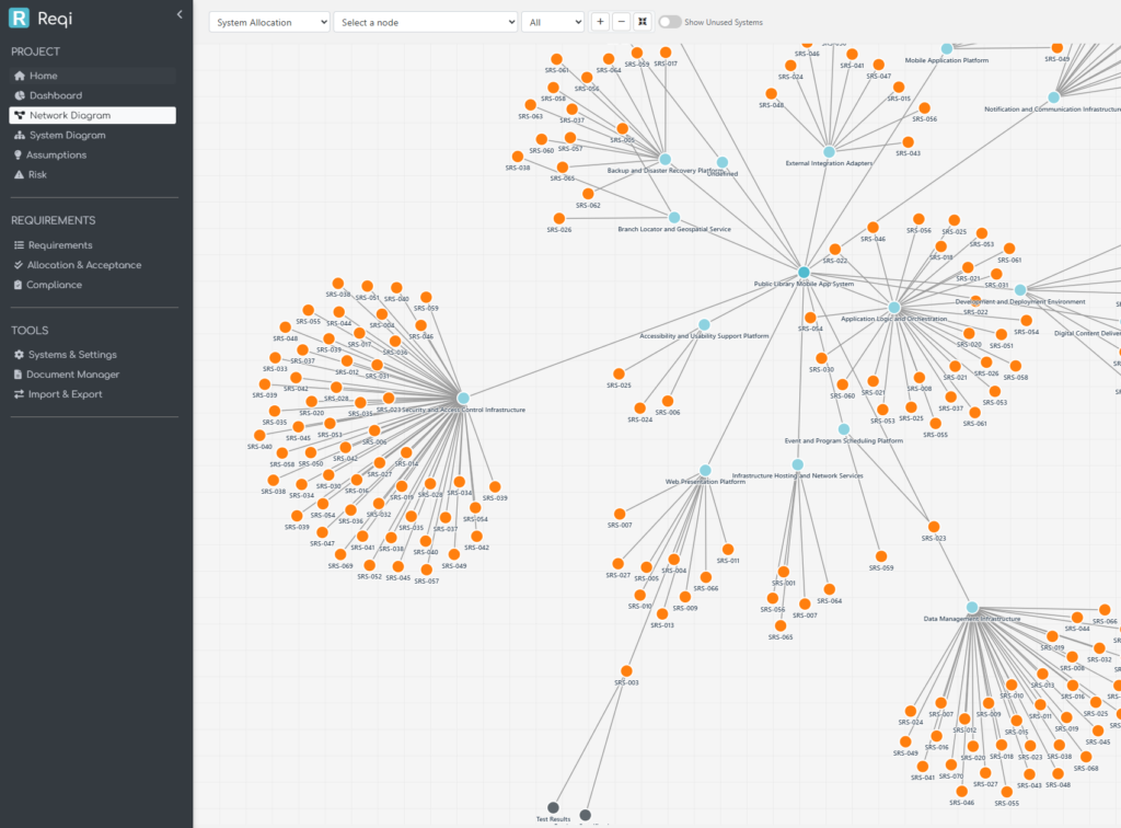
1. The Systems Diagram: a canvas for system architecture
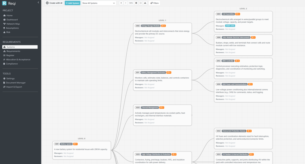
The Systems Diagram page is the new home for a project’s system breakdown. Each box is a system; each line is a parent / child relationship in the hierarchy. The canvas supports zoom, pan, drag-to-move, and a per-project saved layout — open the page tomorrow and your tree is exactly where you left it.
A few engineering decisions are baked in:
- One canonical breakdown per project. Every system has at most one parent (
parent_system_id). The canvas does not draw multi-parent edges, because a multi-parent breakdown is, by INCOSE’s single taxonomy rule, no longer a breakdown — it’s a different cut of the system viewed two ways. If you need that, model the second cut as a separate concern (interfaces, deployment, etc.); the architecture tree stays one tree. - Levels are 1-indexed, root first. The System of Interest sits at Level 1 with the deeper teal colour the rest of the app uses for the project root. The Level-1 system is the SoI — it’s not a separate “project” pseudo-node above it.
- Active vs inactive is hierarchical. A system is “active” if it (or any descendant) has at least one allocated requirement. The colour-coding cascades up the tree, so you can see at a glance which branches still have ungrounded boxes.
Drawing it by hand
The manual flow is direct. + Add System drops a new box into the project; click into it to set the name, description, and parent. The AI button beside it (for organisations with REX AI enabled) opens the architecture generator instead. Both feed into the same database — there’s no “AI mode” parallel universe.
For a pre-existing tree, drag any box to reposition it; the new layout is saved per-project so your team sees the same arrangement. Hover the box to reveal a + Add chip in the corner that creates a child system one click away.
Generating it with AI
Click Create with AI and you describe the project in prose. You can also upload supporting documents (.txt, .csv, .docx, .pdf, .xls, .xlsx); the page extracts text client-side using mammoth.js, pdf.js, and SheetJS so the documents never leave your browser unprocessed.
What the AI is told to do — and where INCOSE shows up — is the interesting part. The pipeline runs per level:
- Pass 1 elicits the SoI’s Level 1 children directly from the context and supporting documents. The model is constrained to produce 5 to 9 children (Miller’s Law: 7 ± 2). It’s also given a derived context — a ≤150-word summary of what the AI inferred about the SoI, scope, and decomposition taxonomy — which it then re-uses for every subsequent level so there’s no need to re-send the heavy supporting documents on every call.
- Passes 2…N expand each Level-(N) parent into its own children. The same 5–9 rule applies. Two parents are expanded in parallel with linear backoff retry on transient gateway errors.
Two INCOSE rules drive this:
- The 100 % rule. A parent’s children must collectively cover everything the parent does. The prompt asks the model to verify this for each parent before accepting the expansion.
- The 7 ± 2 rule. Beyond about nine children, humans stop being able to reason about the breakdown holistically. The model is told to push deeper rather than fan wider; an overcrowded level is decomposed in the next pass.
The result is a draft tree. You preview it before anything is written to the database, and you choose Append (add alongside existing systems) or Overwrite (start fresh). At any point you can hit Stop and the partial tree is offered as a preview.
Value to the systems engineer
Three concrete things change in your day:
- Architectures are visible during requirement work, not after. A requirement without a home is now a missing line on a picture, not a row in a spreadsheet you have to scroll to.
- Drafting is fast, decomposition is the hard part. The AI gets the obvious decomposition out of the way — physical layers, common subsystems, regulatory categories — and frees you to think about the parts that actually need engineering judgement.
- The SoI is named and held still. INCOSE’s most-stepped-on rule in early projects is letting the SoI drift. The page calls it out, prefills the project name, and shows you a derived SoI summary before generating anything below Level 1.
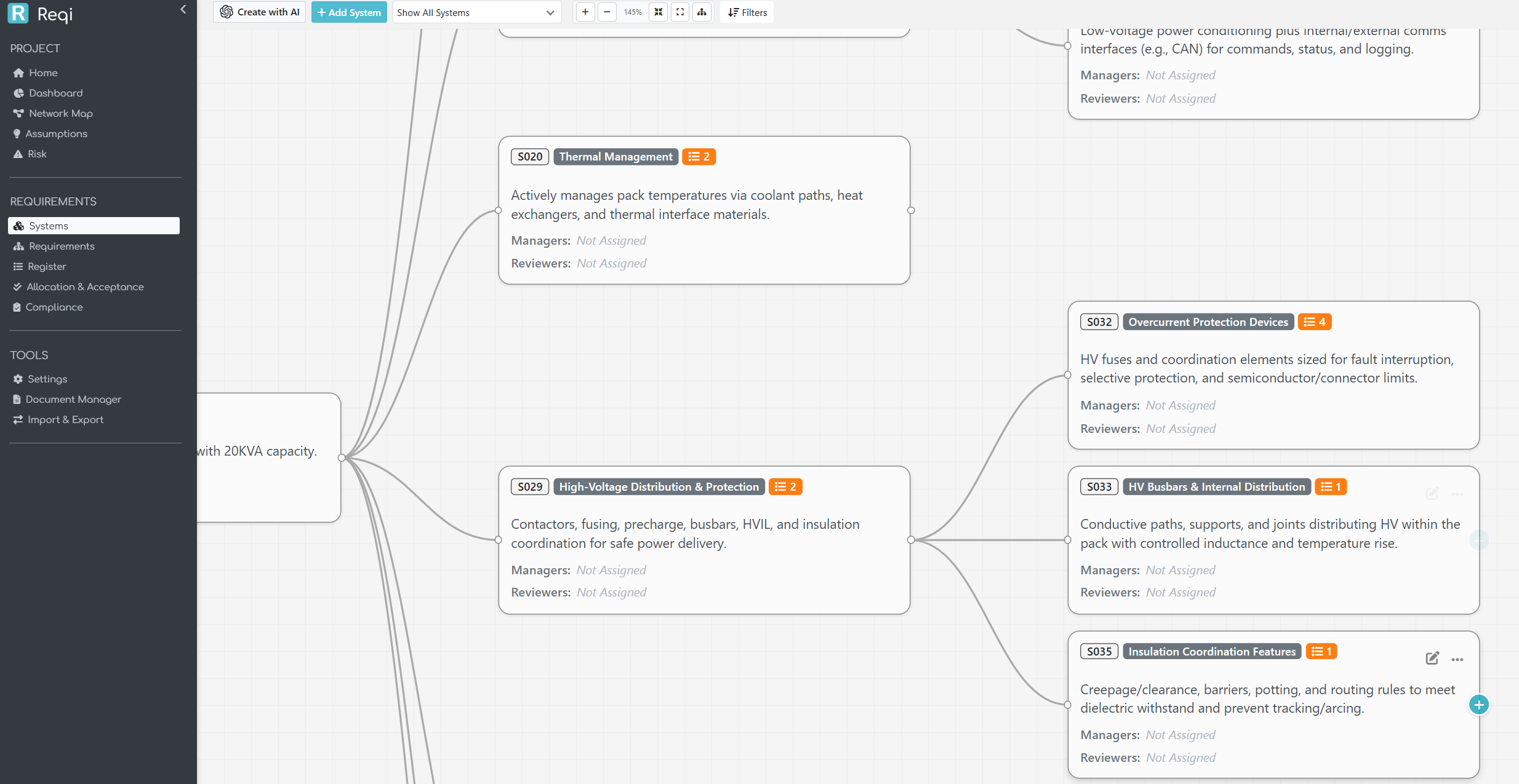
2. The Requirements Diagram: a system, its requirements, and the room to add more
The Requirements Diagram is the inverse view: instead of looking at the system tree alone, you see each system as a container, with its allocated requirements rendered as cards inside it.
You can flip between two layouts:
- Systems toggle ON — columns are system levels. Each system is a parent box, requirements stack inside as cards, system parent / child wires connect the boxes. This is the architecture-first view: it answers “what does this subsystem have to do?”
- Systems toggle OFF — columns are requirement-derivation levels (root requirements at Level 1, derived children at Level 2 and below). This is the engineering-flow view: it answers “how does this requirement decompose?”
Both views support the same actions. Click any requirement card to edit. Hover any system parent to reveal a + Add chip; clicking it opens the requirement-add modal with that system pre-selected, so the new requirement lands directly in the right box. Filtering by a single requirement reduces the canvas to that requirement’s allocation chain — every system it touches, every parent / derived requirement it relates to.
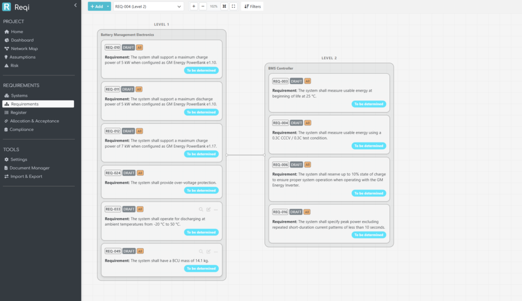
A small but useful detail: in System-toggle-OFF mode, when a column has multiple requirements that all share the same system, the page draws a tight group box around them with the system name on the title bar — the system context is preserved even though the layout is requirement-first.
3. AI requirement elicitation: an INCOSE procedure in a prompt
The new Create with AI button on the requirements page generates a draft requirement set directly from the project context and any supporting documents you upload. This isn’t free-form prompting; the prompt is structured around INCOSE’s elicitation procedure (§4.2 Stakeholder Needs and Requirements Definition, §4.4 System Requirements Definition).
The model is told, in order:
- Identify the system of interest and the stakeholders implied by the context and documents.
- Capture each stakeholder’s needs — what they expect from the system.
- Translate each need into one or more atomic system requirements written as shall statements.
- Verify each requirement against the standard INCOSE quality criteria:
- Atomic — one shall per requirement; no compound and / or clauses.
- Unambiguous — a single, clear interpretation.
- Verifiable — testable, inspectable, analysable, or demonstrable.
- Solution-free — what the system must do, not how.
- Necessary — every requirement traces back to a stakeholder need or a source clause in the documents.
- Cover the full requirement taxonomy — functional, performance, interface, environmental, safety, security, regulatory, operational.
- Preserve clause / source codes from the source documents in a
req_allocationfield, so traceability back to the source material is automatic.
A subtle detail that makes the result more complete: even though allocation is performed in a separate, dedicated step, the project’s system architecture is passed to the elicitation prompt as coverage context. The model is told not to allocate, but to use the subsystem catalogue as a checklist — for each subsystem, are there any obvious functional, performance, interface, environmental, safety, security, regulatory, or operational requirements I have missed? This drops the “blind spot” failure mode where an early elicitation pass fixates on the topics the user happened to mention in the context and quietly skips the boring-but-important subsystems.
How the engine runs
The actual call to the model runs out-of-band. The browser sends a small POST to start the job, and the server spawns a detached worker process to do the OpenAI call. The browser then polls a tiny status endpoint every two seconds. This avoids the gateway timeouts that synchronous AI requests suffer when the model takes longer to respond than the upstream is willing to wait for.
When the worker finishes, the browser streams the requirements into the preview list one at a time so the user gets visible progress instead of a long blank wait followed by an avalanche. From there it’s the same story as the architecture flow — review, choose Append or Overwrite, click Insert.
Value to the systems engineer
The honest description of what this does to your day: it produces a credible first draft. You will edit it. But the gap between blank requirements page and first draft to argue with is where most of the calendar time disappears, and the AI closes that gap in minutes rather than days. Because the prompt is INCOSE-shaped, the draft tends to fail in the same places a junior engineer’s draft fails — too few interface requirements, missing environmental constraints — and you can spot and fix those in review rather than reverse-engineering bad prose into good shall statements.
4. AI system allocation: lowest-level capable, every time
The third AI tool is Allocate Systems with AI, available from the requirement-action panel. Pick any number of requirements, click Allocate Systems with AI, and the AI assigns each one to the right subsystem in the project’s architecture.
This sounds easy but it’s the place where naive allocation tools fail in the same way every time: everything ends up at Level 1. The reason is structural — Level 1 systems have broad names that match almost any requirement loosely, so a model that tries to maximise relevance across all candidates will keep picking the highest, broadest match.
INCOSE has a clear rule for this (§4.4–§4.5):
Requirements are allocated to the lowest-level system element capable of satisfying them. The deepest level in your architecture is checked by default; widen the scope only when a requirement is genuinely cross-cutting across higher-level elements.
Reqi’s allocation prompt is built directly around that sentence. The decision procedure the model is told to apply, per requirement, is:
- Identify the requirement’s subject — what it is about.
- Score every candidate
system_idby semantic / domain match between its name and description and that subject. - Pick the strongest match. When two candidates are equally good, pick the deepest, most specific one — this is the operational form of the “deepest level checked by default” rule.
- Only widen scope to a parent / higher-level element when the requirement is genuinely cross-cutting (e.g. “all subsystems shall …”, system-wide quality attributes, end-to-end performance budgets).
- Return Unallocated (system_id 999) only when no candidate has any plausible link to the requirement’s subject — not when the model is uncertain between two reasonable candidates. Forcing Unallocated as the “I’m not sure” answer removes the temptation to retreat to a too-broad parent.
The user controls how aggressive the search is via per-level checkboxes: only checked levels are eligible candidates. By default every level is checked, on the principle that letting the model see everything and then constraining its choice with the lowest-level-first rule is more reliable than asking the user to narrow the scope manually.
The allocation runs one requirement at a time, with the system tree (names + descriptions) sent on every call so the model has the same architectural context on every decision. The progress modal lists each requirement as it resolves and shows a badge for the chosen system, with a hover popover carrying the system’s full description — exactly the same .badge-system markup the rest of the application uses, so the visual language is consistent.
When the run finishes, the breakdown panel groups the allocations by system — a quick scan tells you whether the AI tipped too many requirements into one subsystem, or whether a particular subsystem still has zero matches and probably needs decomposition. Append or Replace mode lets you layer the AI’s output on top of an existing manual allocation rather than blowing it away.
Value to the systems engineer
This is the feature that pays back the most calendar time. Manual allocation across a few hundred requirements is genuinely a multi-day exercise in tedium, and the cost of a mis-allocation isn’t just one bad row — it’s a downstream verification activity that ends up in the wrong subsystem’s plan, with the wrong owner, and probably the wrong evidence record. Pushing the allocation through a prompt that explicitly enforces lowest-level capable, deepest level first means the failure mode you’re left to clean up is the one humans handle best — debating two near-tied subsystems — instead of the one humans handle worst — verifying that 300 requirements aren’t all sitting on the SoI.
5. Stitching it together: how the four pieces compose
The four pieces are designed to compose into a single workflow:
- Architect — generate the SoI breakdown with Create System Architecture with AI, refine it on the Systems Diagram canvas.
- Elicit — generate the requirement set with Create Requirements with AI, with the architecture passed in as coverage context so the requirements span every subsystem area.
- Allocate — push the requirements into the architecture with Allocate Systems with AI, INCOSE’s lowest-level rule enforced in the prompt.
- Drill in — use the Requirements Diagram to pivot between system view and derivation view, edit individual requirements, and add new ones in place where the architecture shows a gap.
Each step is independent — you can hand-author any piece, and you can stop at any point — but the integration matters. Architecture decisions inform requirement coverage; requirement decisions inform allocation; allocation decisions surface architecture gaps. Tools that treat these as separate disciplines end up encouraging a waterfall — finish the architecture, then write the requirements, then allocate them — that doesn’t match how systems engineering actually proceeds. Reqi’s update is built on the assumption that you’ll loop through the four steps several times before declaring any of them finished, and that the AI should accelerate each loop rather than gate it behind a phase boundary.
What’s next
A few things are deliberately not in this update — interface management, formal N²-matrix views, and a separate model for Acceptance Criteria (currently a sub-type of requirement). The reasoning is the same in each case: introducing those features properly requires architectural changes that would land less cleanly if rushed in alongside the AI work. They’re tracked, and the foundation laid here — particularly the parent / child architecture model and the polled-worker pattern for long AI calls — is what makes them straightforward when their turn comes.
The bigger pattern, though, is the one we wanted to make visible in this release: using AI to operationalise INCOSE, rather than to replace it. The model isn’t being asked to invent engineering practice — it’s being asked to apply a documented method, with the method itself encoded in the prompt and visible in the comments alongside it. That makes the system auditable: if a generated requirement is wrong, or an allocation lands in the wrong subsystem, the procedure that produced it is traceable, in plain English, in the source. For a discipline whose value depends on traceability, that’s the part that mattered most.
Reqi is a requirements management application maintained by Mike. Feedback on this update is welcome — the AI prompts in particular are tuned iteratively against real project feedback, and a project that surfaces a failure mode we haven’t seen yet is more valuable than ten that work first time.